FreeCore Function #13:
Corner
Bender
Module name: corner
Current release:
version 1.0, December 23rd, 1997
Contributed by: mailto:idr@ee.ed.ac.uk
MODULE APPLICATIONS:
(1) Image processing - i.e. splitting an N bit image channel into N separate
bitplanes.
(2) PCM (Pulse Code Modulation)
INTRODUCTION
(1) This LPM function was developed to permit the most efficient separation of the component bitplanes in an image for display on a fast binary array modulator, using pulse width modulation (see http://www.ee.ed.ac.uk/~idr/research.html). The function has an N clock cycle latency, where N is the number of bitplanes in a pixel for separation.
(2) As it also happens, the algorithm behind this function is very common and can be found embedded (with a fixed architecture) in most digital telephony systems. The function enables the efficient Pulse Code Modulation (PCM) of data for digital transmission. This technique, which is sometimes known as logarithmic encoding or m -Law is the US and Japan, provides the most efficient method of transmitting time-multiplexed data on many channels (i.e. permits the multiplexing of many simultaneous telephone conversations on a small number of channels).
HOW IT WORKS
The corner bender consists of an N x N array of flip-flops, where N is the number of channels (or bitplanes) to be formatted. In the case of an 8-bit image from a frame grabber, an 8 x 8 corner bender is required.
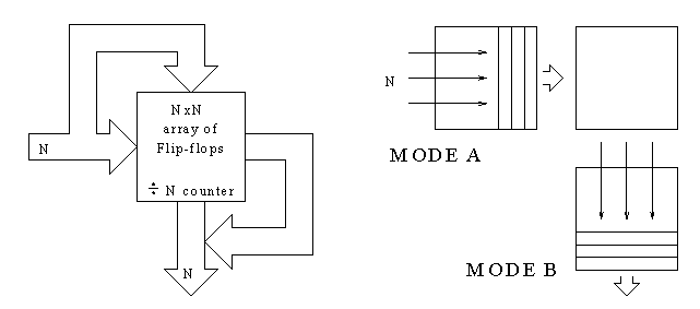
A common clock drive all the flip-flops organised in the array (see figure 1). In mode A, each flip-flop receives data from the left whereas in mode B each flip-flop receives data from above. For the first N clock cycles, the array is in mode A receiving N bit streams and right-shifting them into the array. For the next N clocks pulses the array is in mode B, down-shifting the complete array (N x N bits). During this time, new data can be shifted in from one side while processed data is shifted out the opposite side. After a further N clock cycles, the mode control is again changed to A and the remaining data is entered from the left. The mode control is derived from a divide-by-N (or Freecores div_by_n function) counter.

Figure 1: Corner bender algorithm.
NOTE: It should noted that the corner bender function is symmetrical in the sense that formatted data can also be converted back to its original structure using an identical arrangement to the original encoder (see next section).
TESTING
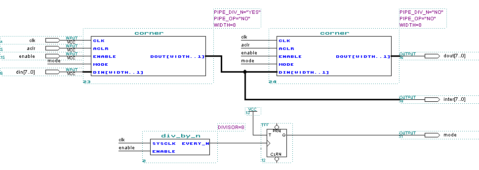
The simplest method of checking the functionality of a corner bender is to join two identical corner benders together (see figures 2a and b). The combined arrangement is analogous to a PCM Tx and Rx system. An input test vector (random or counter value) is reproduced 2N clock cycles later thus confirming its operation.
Figure 3 shows the result of a waveform simulation of the arrangement described in figure 2b. An input test vector, an 8 bit count value is applied to an 8x8 corner bender. The intermediate value, inter[7..0], contains the separated components. It is at this juncture that separate image bitplanes can be siphoned off for storage/further processing or sent directly to a fast binary display (Spatial Light Modulator).

Figure 2a: Test arrangement for an 8x8 corner bender.

Figure 2b: MAX+PLUS II test arrangement for an 8x8 corner bender

Figure 3: Waveform timing scheme.
MODULE DESCRIPTION
| PARAMETERS | OPTIONS | FUNCTION |
| PIPE_DIV_N | "YES" or "NO" |
Pipelines the input to the corner bender so as to make it compatible with div_by_n (mode controller). |
| PIPE_OP | "YES" or "NO" |
Pipelines the output of the corner bender. This may not be required, as processed data will probably be further sampled. |
| WIDTH | 1 to N |
Corner bender size - an N x N array will be generated. |
| INPUT PORTS | ||
| clk | System input clock (flip-flop array is positive edge triggered) | |
| aclr | Asynchronous clear (active high) | |
| enable | Enables the corner benders flip-flop array (active high) | |
| mode | Flip-flop array direction shift control | |
| din[WIDTH..1] | Input data bus | |
| OUTPUT PORTS | ||
| dout[WIDTH..1] | Output data bus | |
![]()
Last updated 08 Feb 2001 11:53